Ethernet over Fibre Channel

Since the 80’s, Ethernet has dominated the networking world. The LAN, the WAN, and the MAN are all now dominated by Ethernet links. FIDDI, HIPPI, ATM, Frame Relay, they’ve all gone by the wayside. But there is one protocol that has stuck around to run alongside Ethernet, and that’s Fibre Channel. While Fibre Channel has mostly sat in the shadow of Ethernet, relegated to only storage traffic, it’s now poised to overtake Ethernet in the battle for the LAN. And the way that Fibre Channel is taking on Ethernet is with Ethernet over Fibre Channel.

Slide2

Suck it, Metcalfe

While Ethernet has enjoyed tremendous popularity, it has several (debilitating) limitations. For one, forwarding is haunted the possibility of a loop, and Spanning Tree Protocol is required to keep a watchful eye. Unfortunately, STP is almost as bad as a loop, with the ample opportunity for misconfigurations (rouge root bridges) and other shenanigans.  TRILL, a Layer 2 overlay for Ethernet that allows multi-pathing, hasn’t found its way into a commercial product yet, and its derivatives (FabricPath from Cisco and VCS from Brocade) haven’t seen much in the way of adoption.

Rathern than pile fix upon fix on Ethernet, SAN administrators (known for being the loose canons of the data center) are making a bold push to take over LAN networks as well… and they’re winning.

The T17 committe had been established by the INCITS, which is the standards body that is responsible for Fibre Channel, FCoE, and now EoFC. The T17 is responsible for all the specifications around EoFC, and in particular the interface between the two.

We really have a lot of advantages over Ethernet in terms of topology and forwarding. For one, we’re a lossless network, providing a lot more reliability than a traditional Ethernet network. We also have multi-pathing built in with FSPF routing, while still providing Layer 2 adjacencies that are still required by the old crusty crapplications that are still on people’s networks, somehow.” -John Etherman, T17 committee chair.

They’ve made a lot of progress in a relatively short time, from ironing out the specifications to getting ASICs spun, and their work is bearing fruit. Products are starting to ship, and several marquee clients have announced fabrics built entirely with EoFC.

A Day in the life of a EoFC Frame

To keep compatibility with older Ethernet/TCP/IP stacks, CNHs (Converged Network HBAs) provide Ethernet interfaces to the host operating system. The frame is formed by the host, and the CNH encapsulates the Ethernet frame into a Fibre Channel frame. Since standard Ethernet MTU is only 1500 bytes, they fit quite nicely into the maximum 2048 byte Fibre Channel frame. The T13 working group also provides specifications for Jumbo Ethernet frames up to 9216 bytes, by either fragmenting the frame into multiple 2048-byte Fibre Channel frames,

WWPNs are derived from the MAC addresses that the hosts sees. Since MAC addresses aren’t a full 64-bits, the T17 working group has allocated the 80:08 prefix to EoFC. So if your MAC address was 00:25:B6:01:23:45, the WWPN would be 80:08:00:25:B6:01:23:45. This keeps the EoFC WWPNs out of the range of the initiators (starting with 1 or 2) and targets (starting with 5).

EoFC

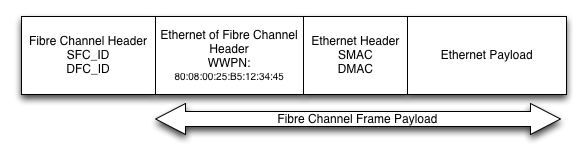
FC_IDs are assigned to the WWPNs on a transitory basis, and are what the Fibre Channel headers have in terms of source/destination addresses. When the Fibre Channel frame reaches its destination NX_Port (Node LAN port), the Ethernet frame is de-encapsulated from the Fibre Channel frame, and the hosts networking stack takes care of the rest. From a host’s perspective, it has no idea the transport is Fibre Channel.

Reliability

The biggest benefit to EoFC is the lossless network that Fibre Channel provides. Since the majority of traffic is East/West in modern data center workloads, busy hosts can suffer from an incast problem, where the buffers can be overloaded as a single 10 Gigabit link receives packets from multiple sources, all operating at 10 Gigabit. Fibre Channel transport provides port to port flow control, and can ensure that nothing gets dropped.

Configuration

Configuration of EoFC is fairly straightforward. I’ve got access to a new Nexus 8008, with a 32 Gbit EoFC line card that I’ve connected to a Cisco C-series server with a CNH.

nexus1# feature eofc
EoFC feature checked out
Loading Ethernet module...
Loading Spanning Tree module...
Loading LLDP...
Grace period license remaining: 110 days

nexus1# vlan 10
nexus1(vlandb)# vsan 10
nexus1(vsandb)# 10 name Storage-A
nexus1(vsandb)# vsan 1010
nexus1(vsandb)# vsan 1010 name Ethernet transport
nexus1(vsandb)# eofc vlan 10
nexus1(vsandb)# interface veth1
nexus1(vif)# switchport
nexus1(vif)# switchport mode access
nexus1(vif)# switchport access vlan 10
nexus1(vif)# bind interface fc1/1
nexus1(vif)# no shut
nexus1(vif)# int fc1/1
nexus1(if)# switchport mode F
nexus1(if)# switchport allowed vsan 10,1010
nexus1(if)# no shut 

Doing a show interface shows me that my connection is live.

 nexus1# show interface ethernet veth1 
 vEthernet1 is up
 Hardware: 1000/10000 Ethernet, address: 000d.ece7.df48 (bia 000d.ece7.df48)
 Attached to: fc1/1 (pWWN: 80:08:00:0D:EC:E7:DF:48)
 MTU 1500 bytes, BW 10000000 Kbit, DLY 10 usec,
 reliability 255/255, txload 1/255, rxload 1/255
 Encapsulation EoFC/ARPA
 Port mode is EoFC
 full-duplex, 32 Gb/s, media type is 1/2/4/8/16/32g
 Beacon is turned off
 Input flow-control is off, output flow-control is off
 Rate mode is dedicated
 Switchport monitor is off
 Last link flapped 09:03:57
 Last clearing of "show interface" counters never
 30 seconds input rate 2376 bits/sec, 0 packets/sec
 30 seconds output rate 1584 bits/sec, 0 packets/sec
 Load-Interval #2: 5 minute (300 seconds)
 input rate 1.58 Kbps, 0 pps; output rate 792 bps, 0 pps
 RX
 0 unicast packets 10440 multicast packets 0 broadcast packets
 10440 input packets 11108120 bytes
 0 jumbo packets 0 storm suppression packets
 0 runts 0 giants 0 CRC 0 no buffer
 0 input error 0 short frame 0 overrun 0 underrun 0 ignored
 0 watchdog 0 bad etype drop 0 bad proto drop 0 if down drop
 0 input with dribble 0 input discard
 0 Rx pause
 TX
 0 unicast packets 20241 multicast packets 105 broadcast packets
 20346 output packets 7633280 bytes
 0 jumbo packets
 0 output errors 0 collision 0 deferred 0 late collision
 0 lost carrier 0 no carrier 0 babble
 0 Tx pause
 1 interface resets
 switch#

Speeds and Feeds

EoFC is backwards compatible with 1/2/4/8 and 16 Gigabit Fibre Channel, but it’s really expected to take off with the newest 32/128 Gbit interfaces that are being released from vendors like Cisco, Juniper, and Brocade. Brocade, QLogix, Intel, and Emulex are all expected to provide CNHs operating at 32 Gbit speeds, with 32 and 128 Gbit interfaces on line cards and fixed switches to operate as ISLs.

Nexus 8009

Nexus 8008: 384 ports of 32 Gbit EoFC

Switches are already shipping from Cisco and Brocade, with Juniper to release their newest QFC line before the end of Q2.

OTV AEDs Are Like Highlanders

While prepping for CCIE Data Center and playing around with a lab environment, I ran into a problem I’d like to share.

I was setting up a basic OTV setup with three VDCs running OTV, connecting to a core VDC running the multicast core (which is a lot easier than it sounds). I’m running it in a lab environment we have at Firefly, but I’m not going by our normal lab guide, instead making it up as I go along in order to save some time, and make sure I can stand up OTV without a lab guide.

Each VDC will set up an adjacency with the other two, with the core VDC providing unicast and multicast connectivity.  That part was pretty easy to setup (even the multicast part, which had previously freaked me the shit out). Each VDC would be its own site, so no redundant AEDs.

On each OTV VDC, I setup the following as per my pre-OTV checklist:

  • Bi-directional IPv4 unicast connectivity to each join interface (I used a single OSPF area)
  • MTU of 9216 end-to-end (easy since OTV requires M line cards, and it’s just an MTU command on the interface)
  • An OTV site VLAN which requires:
    • That the VLAN is configured on the VDC
    • That the VLAN is active on a physical port that is up
  • Multicast configuration
    • IP pim sparse-mode configuration on every interface, end-to-end
    • IP igmp version 3 on every interface end-to-end
    • Rendezvous point (RP) configured on the loopback address of the core VDC (I used the bidir tag)

So I got all that configured and then configured the OTV setup. Very basic:

feature otv

otv site-vlan 10

interface Overlay1
  otv join-interface Ethernet1/2
  otv control-group 239.1.1.1
  otv data-group 232.1.1.0/28
  otv extend-vlan 100
  no shutdown
otv site-identifier 0000.0000.0002

ip pim rp-address 10.11.200.1 group-list 224.0.0.0/4
ip pim ssm range 232.0.0.0/8

The only difference between the three OTV VDC configurations was the site-identifier and the join interface. Everything else was identical, pretty easy configuration. But… it didn’t work. Shit. Time for some show commands:

N7K-11-vdc-2# show otv adjacency
Overlay Adjacency database
Overlay-Interface Overlay1 :
Hostname System-ID Dest Addr Up Time State
VDC-3 18ef.63e9.5d43 10.11.3.2 01:36:52 UP
vdc-4 18ef.63e9.5d44 10.11.101.2 01:41:57 UP
vdc-2#

OK, so the adjacencies are built. I’ve at least got IP4 unicast and multicast going on. How about “show otv”?

N7K-11-vdc-2# show otv

OTV Overlay Information
Site Identifier 0000.0000.0002

Overlay interface Overlay1

 VPN name : Overlay1
 VPN state : UP
 Extended vlans : 100 (Total:1)
 Control group : 239.1.1.1
 Data group range(s) : 232.1.1.0/28
 Join interface(s) : Eth1/2 (10.11.2.2)
 Site vlan : 11 (up)
 AED-Capable : No (Site-ID mismatch)
 Capability : Multicast-Reachable
N7K-11-vdc-2#

Site-ID mismatch? What the shit? They’re supposed to mismatch. I try another command:

N7K-11-vdc-2# show otv site

Dual Adjacency State Description
 Full - Both site and overlay adjacency up
 Partial - Either site/overlay adjacency down
 Down - Both adjacencies are down (Neighbor is down/unreachable)
 (!) - Site-ID mismatch detected

Local Edge Device Information:
 Hostname vdc-2
 System-ID 18ef.63e9.5d42
 Site-Identifier 0000.0000.0002
 Site-VLAN 11 State is Up

Site Information for Overlay1:

Local device is not AED-Capable (Site-ID mismatch)
Neighbor Edge Devices in Site: 1

Hostname System-ID Adjacency- Adjacency- AED-

 State Uptime Capable

--------------------------------------------------------------------------------
VDC-3 18ef.63e9.5d43 Partial (!) 00:17:39 Yes

Now this show command confused me for a while. I was trying to figure out the Site-ID mismatch. I was also wondering why I could see VDC-3 but couldn’t see VDC-4. Then it dawned on me (after am embarrassing amount of time) I’m not supposed to. I’m not supposed to see VDC-3, either. The “show site” command is only looking at the local area. For my configuration, I shouldn’t see any other VDCs with “show otv site”.

This means that there’s some type of Layer 2 connectivity between the different sites. VDC-3 and VDC-4 both somehow see each other as Layer 2 adjacent. That shouldn’t happen if they’re supposedly on remote sites. This is a lab environment, so there’s some sort of Layer 2 connectivity for the Site-VLAN that I need to kill.

OTV edge devices are like highlanders, if there’s Layer 2 adjacency, they sense each other.

highlander9

“I could sense you by your VLAN”

It probably happened on the interface that I assigned the site-VLAN to as an access port. A VLAN will not show “active” unless you have an active physical link (interface VLANs don’t count).

So I went through and re-configured the site VLAN. Instead of VLAN 10 (which was probably active on the other ends of those interfaces somehow) I created new VLANs, and used a unique VLAN for each VDC. The site-VLANs do not need to be identical between sites. I put the VLAN on a physical link that was up, and voila.

In the real world, you probably won’t run into this. However, it’s possible if there are other Layer 2 interconnects going on in your data center (perhaps dark fiber) or you’re transitioning from one DCI to another, you may hit this.

Fibre Channel: The Heart of New SDN Solutions

From Juniper to Cisco to VMware, companies are spouting up new SDN solutions. Juniper’s Contrail, Cisco’s ACI, VMware’s NSX, and more are all vying to be the next generation of data center networking. What is surprising, however, is what’s at the heart of these new technologies.

Is it VXLAN, NVGRE, Openflow? Nope. It’s Fibre Channel.

Seriously.

If you think about it, it makes sense. Fibre Channel has been doing fabrics since before we ever called Ethernet fabrics, well, fabrics. And this isn’t the first time that Fibre Channel has shown up in unusual places. There’s a version of Fibre Channel that runs inside certain airplanes, including jet fighters like the F-22.

1_FW_F-22_Raptor_participates_in_Red_Flag

Keep the skies safe from FCoE (sponsored by the Evaluator Group)

New generation of switches have been capable of Data Center Bridging (DCB), which enables Fibre Channel over Ethernet. These chips are also capable of doing native Fibre Channel So rather than build complicated VPLS fabrics or routed networks, various data center switching companies are leveraging the inherent Fibre Channel capabilities of the merchant silicon and building Fibre Channel-based underlay networks to support an IP-based overlay.

Buffer-to-buffer (B2B) credit system and losslessness of Fibre Channel, plus the new 32/128 Gigabit interfaces with the newest Fibre Channel standard are all being leveraged for these underlays. I find it surprising that so many companies are adopting this, you’d think it’d be just Brocade. But Cisco, Arista (who notoriously shunned FCoE) and Juniper are all on board with new or announced SDN offerings that are based mostly or in part on Fibre Channel.

However, most of the switches from various vendors are primarily Ethernet today, so the 10/40 Gigabit interfaces can run FCoE until more switches are available with native FC interfaces. Of course, these switches will still be required to have a number of native Ethernet ports in order to connect to border networks that aren’t part of the overlay network, so there will be still a need for Ethernet. But it seems the market has spoken, and they want Fibre Channel.


Hey, Remember vTax?

Hey, remember vTax/vRAM? It’s dead and gone, but with 6 Terabyte of RAM servers now available, imagine what could have been (your insanely high licensing costs).

Set the wayback machine to 2011, when VMware introduced vSphere version 5. It had some really great enhancements over version 4, but no one was talking about the new features. Instead, they talked about the new licensing scheme and how much it sucked.

wayback2

While some defended VMware’s position, most were critical, and my own opinion… let’s just say I’ve likely ensured I’ll never be employed by VMware. Fortunately, VMware came to their senses and realized what a bone-headed, dumbass move that vRAM/vTax was, and repealed the vRAM licensing one year later in 2012. So while I don’t want to beat a dead horse (which, seriously, disturbing idiom), I do think it’s worth looking back for just a moment to see how monumentally stupid that licensing scheme was for customers, and serve as a lesson in the economies of scaling for the x86 platform, and as a reminder about the ramifications of CapEx versus OpEx-oriented licensing.

Why am I thinking about this almost 2 years after they got rid of vRAM/vTax? I’ve been reading up on the newly released Intel’s E7 v2 processors, and among the updates to Intel’s high-end server chip is the ability to have 24 DIMMs per socket (the previous limit was 12) and the support of 64 GB DIMMs. This means that a 4-way motherboard (which you can order now from Cisco, HP, and others) can support up to 6 TB of RAM, using 96 DIMM slots and 64 GB DIMMs. And you’d get up to 60 cores/120 threads with that much RAM, too.

And I remembered one (of many) aspects about vRAM that I found horrible, which was just how quickly costs could spiral out of control, because server vendors (which weren’t happy about vRAM either) are cramming more and more RAM into these servers.

The original vRAM licensing with vSphere 5 was that for every socket you paid for, you were entitled to/limited to 48 GB of vRAM with Enterprise Plus. To be fair the licensing scheme didn’t care how much physical RAM (pRAM) you had, only how much of the RAM was consumed by spun-up VMs (vRAM). With vSphere 4 (and the current vSphere licensing, thankfully), RAM had been essentially free: you only paid per socket. You could use as much RAM as you could cram into a server.  But with the vRAM licensing, if you had a dual-socket motherboard with 256 GB of RAM you would have to buy 6 licenses instead of 2. At the time, 256 GB servers weren’t super common, but you could order them from the various server vendors (IBM, Cisco, HP, etc.). So with vSphere 4, you would have paid about $7,000 to license that system. With vSphere 5, assuming you used all the RAM, you’d pay about $21,000 to license the system, a 300% increase in licensing costs. And that was day 1.

Now lets see how much it would cost to license a system with 6 TB of RAM. If you use the original vRAM allotment amounts from 2011, each socket granted you 48 GB of vRAM with Enterprise Plus (they did up the allotments after all of the backlash, but that ammended vRAM licensing model was so convoluted you literally needed an application to tell you how much you owed). That means to use all 6 TB (and after all, why would you buy that much RAM and not use it), you would need 128 socket licences, which would have cost $448,000 in licensing. A cluster of 4 vSphere hosts would cost just shy of $2 million to license. With current, non-insane licensing, the same 4-way 6 TB server costs a whopping $14,000. That’s a 32,000% price differential. 

Again, this is all old news. VMware got rid of the awful licensing, so it’s a non-issue now. But still important to remember what almost happened, and how insane licensing costs could have been just a few years later.

saved

My graph from 2011 was pretty accurate.

Rumor has it VMware is having trouble getting customers to go for OpEx-oriented licensing for NSX. While VMware hasn’t publicly discussed licensing, it’s a poorly kept secret that VMware is looking to charge for NSX on a per VM, per month basis. The number I’d been hearing is $10 per month ($120 per year), per VM. I’ve also heard as high as $40, and as low as $5. But whatever the numbers are, VMware is gunning for OpEx-oriented licensing, and no one seems to be biting. And it’s not the technology, everyone agrees that it’s pretty nifty, but the licensing terms are a concern. NSX is viewed as network infrastructure, and in that world we’re used to CapEx-oriented licensing. Some of VMware’s products are OpEx-oriented, but their attempt to switch vSphere over to OpEx was disastrous. And it seems to be the same for NSX.

Changing Data Center Workloads

Networking-wise, I’ve spent my career in the data center. I’m pursuing the CCIE Data Center. I study virtualization, storage, and DC networking. Right now, the landscape in the network is constantly changing, as it has been for the past 15 years. However, with SDN, merchant silicon, overlay networks, and more, the rate of change in a data center network seems to be accelerating.

speed

Things are changing fast in data center networking. You get the picture

Whenever you have a high rate of change, you’ll end up with a lot of questions such as:

  • Where does this leave the current equipment I’ve got now?
  • Would SDN solve any of the issues I’m having?
  • What the hell is SDN, anyway?
  • I’m buying vendor X, should I look into vendor Y?
  • What features should I be looking for in a data center networking device?

I’m not actually going to answer any of these questions in this article. I am, however, going to profile some of the common workloads that you find in data centers currently. Your data center may have one, a few, or all of these workloads. It may not have any of them. Your data center may have one of the workloads listed, but my description and/or requirements is way off. All certainly possible. These are generalizations, and with all generalizations your mileage may vary. With that disclaimer out of the way, strap in. Let’s go for a ride.

Traditional Virtualization

It’s interesting to say that something which only exploded into the data center in a big way in about 2008 as now being “traditional”, rather than “new-fangled”. But that’s the situation we have here. Traditional virtualization workload  is centered primarily around VMware vSphere. There are other traditional virtualization products of course, such as Red Hat’s RHEV, Xen, and Microsoft Hyper-V, but VMware has the largest market share for this by far.

  • Latency is not a huge concern (30 usecs not a big deal)
  • Layer 2 adjacencies are mandatory (required for vMotion)
  • Large Layer 2 domains (thousands of hosts layer 2 adjacent)
  • Converged infrastructures (storage and data running on the same wires, FCoE, iSCSI, NFS, SMB3, etc.)
  • Buffer requirements aren’t typically super high. Bursting isn’t much of an issue for most workloads of this type.
  • Fibre Channel is often the storage protocol of choice, along with NFS and some iSCSI as well

Cisco has been especially successful in this realm with the Nexus line because of vPC, FabricPath, OTV and (to a much lesser extent) LISP, as they address some of the challenges with workload mobility (though not all of them, such as the speed of light). Arista, Juniper, and many others also compete in this particular realm, but Cisco is the market leader.

With the multi-pathing Layer 2 technologies such as SPB, TRILL, Cisco FabricPath, and Brocade VCS (the latter two are based on TRILL), you can build multi-spine leaf/spine networks/CLOS networks that you can’t with spanning-tree based networks, even with MLAG.

This type of network is what I typically see in data centers today. However, there is a shift towards Layer 3 networks and cloud workloads over traditional virtualization, so it will be interested to see how long traditional virtualization lasts.

VDI

VDI (Virtual Desktops) are a workload with the exact same requirements as traditional virtualization, with one main difference: The storage requirements are much, much higher.

  • Latency is not as important (most DC-grade switches would qualify), especially since latency is measured in milliseconds for remote desktop users
  • Layer 2 adjacencies are mandatory (required for vMotion)
  • Large Layer 2 domains
  • Converged infrastructures
  • Buffer requirements aren’t typically very high
  • High-end storage backends. All about the IOPs, y’all

For storage here, IOPs are the biggest concern. VDI eats IOPs like candy.

Legacy Workloads

This is the old, old school. And by old school, I mean late 90s, early 2000s. Before virtualization changed the landscape. There’s still quite a few crusty old servers, with uptimes measured in years, running long-abandoned applications. The problem is, these types of applications are usually running something mission critical and/or significant revenue generating. Organizations just haven’t found a way out of it yet. And hey, they’re working right now. Often running on proprietary Unix systems, they couldn’t or wouldn’t be migrated to a virtualized environment (where it would be much easier to deal with).

The hardware still works, so why change something that works? Because it would be tough to find more. It’s also probably out of vendor-supported service.

  • Latency? Who cares. Is it less than 1 second? Good enough.
  • Layer 2 adjacencies, if even required, are typically very small, typically just needed for the local clustering application (which is usually just stink-out-loud awful)
  • 100 megabit and gigabit Ethernet typically. 10 Gigabit? That’s science-fiction talk!
  • Buffers? You mean like, what shines the floor?

buffers

My own personal opinion is that this is the only place where Cisco Catalyst switches belong in a data center, and even then only because they’re already there. If you’re going with Cisco, I think everything else (and everything new) in the DC should be Nexus.

Cloud Workloads (Private Cloud)

If you look at a cloud workload, it looks very similar to the previous traditional virtualization workload. They both use VMs sitting on top of hypervisors. They both have underlying infrastructure of compute, network, and storage to support these VMs. The difference is primarily is in the operational model.

It’s often described as the difference between pets and cattle. With traditional virtualization, you have pets. You care what happens to these VMs. They have HA and DRS and other technologies to care for them. They’re given clever names, like Bart and Lisa, or Happy and Sleepy. With cloud VMs, they’re not given fun names. We don’t do vMotion/Live Migration with them. When we need them, they’re spun up. When they’re not, they’re destroyed. We don’t back them up, we don’t care if the host they reside on dies so long as there are other hosts carrying the workload. The workload is automatically sharded across the available hosts using logic in the application. Instead of backups, templates are used to create new VMs when the workload increases. And when the workload decreases, some of the VMs get destroyed. State is not kept on any single VM, instead the state of the application (and underlying database) is sharded to the available systems.

This is very different than traditional virtualization. Because the workload distribution is handled with the application, we don’t need to do vMotion and thus have Layer 2 adjacencies. This makes it much more flexible for the network architects to put together network to support this type of workload. Storage with this type of workload also tends to be IP-based (NFS, iSCSI) rather than FC-based (native Fibre Channel or FCoE).

With cloud-based workloads, there’s also a huge self-service component. VMs are spun-up and managed by developers or end-users, rather than the IT staff. There’s typically some type of portal that end-users can use to spin up/down resources. Chargebacks are also a component, so that even in a private cloud setting, there’s a resource cost associated and can be tracked.

OpenStack is a popular choice for these cloud workloads, as is Amazon and Windows Azure. The former is a private cloud, with the later two being public cloud.

  • Latency requirements are mostly the same as traditional virtualization
  • Because vMotion isn’t required, it’s all Layer 3, all the time
  • Storage is mostly IP-based, running on the same network infrastructure (not as much Fibre Channel)
  • Buffer requirements are typically the same as traditional virtualization
  • VXLAN/NVGRE burned into the chips for SDN/Overlays

You can use much cheaper switches for this type of network, since the advanced Layer 2 features (OTV, FabricPath, SPB/TRILL, VCS) aren’t needed. You can build a very simple Layer 3 mesh using inexpensive and lower power 10/40/100 Gbit ports.

However, features such as VXLAN/NVGRE encap/decap is increasingly important. The new Trident2 chips from Broadcom support this now, and several vendors, including Cisco, Juniper, and Arista all have switches based on this new SoC (switch-on-chip) from Broadcom.

High Frequency Trading

This is a very specialized market, and one that has very specialized requirements.

  • Latency is of the utmost concern. To the point of making sure ports are on the same ASIC. Latency is measured in nano-seconds, microseconds are an eternity
  • 10 Gbit at the very least
  • Money is typically not a concern
  • Over-subscription is non-existent (again, money no concern)
  • Buffers are a trade off, they can increase latency but also prevent packet loss

This is a very niche market, one that Arista dominates. Cisco and a few other vendors have small inroads here, using the same merchant silicon that Arista uses, however Arista has had huge experience in this market. Every tick of the clock can mean hundreds of thousands of dollars in a single trade, so companies have no problem throwing huge amounts of money at this issue to shave every last nanosecond off of latency.

Hadoop/Big Data

  • Latency is of high concern
  • Large buffers are critical
  • Over-subscription is low
  • Layer 2 adjacency is neither required nor desired
  • Layer 3 Leaf/spine networks
  • Storage is distributed, sharded over IP

Arista has also extremely successful in this market. They glue PC RAM onto their switch boards to provide huge buffers (around 760 MB) to each port, so it can absorb quite a bit of bursty traffic, which occurs a lot in these types of setups. That’s about .6 seconds of buffering a 10 Gbit link. Huge buffers will not prevent congestion, but they do help absorb situations where you might be overwhelmed for a short period of time.

Since nodes don’t need to be Layer 2 adjacent, simple Layer 3 ECMP networks can be created using inexpensive and basic switches. You don’t need features like FabricPath, TRILL, SPB, OTV. Just fast, inexpensive, low power ports. 10 Gigabit is the bare minimum for these networks, with 40 and 100 Gbit used for connectivity to the spines. Arista (especially with their 7500E platform) does very well in this area. Cisco is moving into this area with the Nexus 9000 line, which was announced late last year.


Conclusions

Understanding the requirements for the various workloads may help you determine the right switches for you. It’s interesting to see how quickly the market is changing. Perhaps 2 years ago, the large-Layer 2 networks seemed like the immediate future. Then all of a sudden Layer 3 mesh networks became popular again. Then you’ve got SDN like VMware’s NSX and Cisco’s ACI on top of that. Interesting times, man. Interesting times.

The Twilight of the Age of Conf T

That sums up the networking world as it exists today. Conf T.

On Cisco gear, that’s the command you type to go into configuration mode, and also a lot of gear that isn’t Cisco. It’s so ingrained in our muscle memory it’s probably the quickest thing any network engineer can type.

On Nexus gear, which runs NX-OS, you don’t need to type the “t” in “conf t”. Typing “conf” will get you into configuration mode, no “T” is required. Same for most other CLIs that employ the “industry standard” CLI that everyone (including Cisco) appropriated.

Yet most of us have it so ingrained in our muscle memory we can’t type “conf” without throwing the “t” at the end. (I had to edit that sentence just to get the “t” out of the first “conf”…. dammit!)

But is that age ending?

VMware released NSX, other companies are releasing their versions of SDN, SDDC, and.. whatever. These are networks that more and more will be controlled not by the manually punching out a CLI, but rather GUI and/or APIs.

We’ve configured networks for the past — what, 20 years — by starting out with “conf t”. And we’ve certainly heard more than one prediction of its demise that turned out to be a flash in the pan. However…

This certainly feels like it could be the beginning of the end of the conf t age. How does something this ubiquitous end?

Gradually, then all of a sudden.

Link Aggregation Confusion

In a previous article, I discussed the somewhat pedantic question: “What’s the difference between EtherChannel and port channel?” The answer, as it turns out, is none. EtherChannel is mostly an IOS term, and port channel is mostly an NXOS term. But either is correct.

But I did get one thing wrong. I was using the term LAG incorrectly. I had assumed it was short for Link Aggregation (the umbrella term of most of this). But in fact, LAG is short for Link Aggregation Group, which is a particular instance of link aggregation, not the umbrella term. So wait, what do we call the technology that links links together?

saymyname

LAG? Link Aggregation? No wait, LACP. It’s gotta be LACP.

In case you haven’t noticed, the terminology for one of the most critical technologies in networking (especially the data center) is still quite murky.

Before you answer that, let’s throw in some more terms, like LACP, MLAG, MC-LAG, VLAG, 802.3ad, 802.1AX, link bonding, and more.

The term “link aggregation” can mean a number of things. Certainly EtherChannel and port channels are are form of link aggregation. 802.3ad and 802.1AX count as well. Wait, what’s 802.1AX?

802.3ad versus 802.1AX

What is 802.3ad? It’s the old IEEE working group for what is now known as 802.1AX. The standard that we often refer to colloquially as port channel, EtherChannels, and link aggregation was moved from the 802.3 working group to the 802.1 working group sometime in 2008. However, it is sometimes still referred to as 802.3ad. Or LAG. Or link aggregation. Or link group things. Whatever.

spaceghost

What about LACP? LACP is part of the 802.1AX standard, but it is neither the entirety of the 802.1AX standard, nor is it required in order to stand up a LAG.  LACP is also not link aggregation. It is a protocol to build LAGs automatically, versus static. You can usually build an 802.1AX LAG without using LACP. Many devices support static and dynamic LAGs. VMware ESXi 5.0 only supported static LAGs, while ESXi 5.1 introduced LACP as a method as well.

Some devices only support dynamic LAGs, while some only support static. For example, Cisco UCS fabric interconnects require LACP in order to setup a LAG (the alternative is to use pinning, which is another type of link aggregation, but not 802.1AX). The discontinued Cisco ACE 4710 doesn’t support LACP at all, instead only static LAGs are supported.

One way to think of LACP is that it is a control-plane protocol, while 802.1AX is a data-plane standard. 

Is Cisco’s EtherChannel/port channel proprietary?

As far as I can tell, no, they’re not. There’s no (functional at least) difference between 802.3ad/802.1ax and what Cisco calls EtherChannel/port channel, and you can set up LAGs between Cisco and non-Cisco without any issue.  PAgP (Port Aggregation Protocol), the precursor to LACP, was proprietary, but Cisco has mostly moved to LACP for its devices. Cisco Nexus kit won’t even support PAgP.

Even in LACP, there’s no method for negotiating the load distribution method. Each side picks which method it wants to do. In fact, you don’t have to have the same load distribution method configured on both ends of a LAG (though it’s usually a good idea).

There is are also types of link aggregation that aren’t part of the 802.1AX or any other standard. I group these types of link aggregation into two types: Pinning, and fake link aggregation. Or FLAG (Fake Link Aggregation).

First, lets talk about pinning. In Ethernet, we have the rule that there can’t be more than one way to get anywhere. Ethernet can’t handle multi-pathing, which is why we have spanning-tree and other tricks to prevent there from being more than one logical way for an Ethernet frame to get from one source MAC to a given destination MAC. Pinning is a clever way to get around this.

The most common place we tend to see pinning is in VMware. Most ESXi hosts have multiple connections to a switch. But it doesn’t have to be the same switch. And look at that, we can have multiple paths. And no spanning-tree protocol. So how do we not melt down the network?

The answer is pinning. VMware refers to this as load balancing by virtual port ID. Each VM’s vNIC has a virtual port ID, and that ID is pinning to one and only one of the external physical NICs (pNICs). To utilize all your links, you need at least as many virtual ports as you do physical ports. And load distributation can be an issue. But generally, this pinning works great. Cisco UCS also uses pinning for both Ethernet and Fibre Channel, when 802.1AX-style link aggregation isn’t used.

It works great, and a fantastic way to get active/active links without running into spanning-tree issues and doesn’t require 802.1AX.

Then there’s… a type of link aggregation that scares me. This is FLAG.

killitwithfire

Some operating systems such as FreeBSD and Linux support a weird kind of link aggregation where packets are sent out various active links, but only received on one link. It requires no special configuration on a switch, but the server is oddly blasting out packets on various switch ports. Transmit is active/active, but receive is active/standby.

What’s the point? I’d prefer active/standby in a more sane configuration.  I think it would make troubleshooting much easier that way.

There’s not much need for this type of fake link aggregation anymore. Most managed switches support 802.1AX, and end hosts either support the aforementioned pinning or they support 802.1AX well (LACP or static). So there are easier ways to do it.

So as you can see, link aggregation is a pretty broad term, too broad to encompass only what would be under the umbrella of 802.1AX, as it also includes pinning and Fake Link Aggregation. LAG isn’t a good term either, since it refers to a specific instance, and isn’t suited as the catch-all term for the methodology of inverse-multiplexing. 802.1AX is probably the best term, but it’s not widely known, and it also includes the optional LACP control plane protocol. Perhaps we need a new term. But if you’ve found the terms confusing, you’re not alone.

EtherChannel and Port Channel

In the networking world, you’ve no doubt heard the terms EtherChannel, port channel, LAG, MLAG, etc. These of course refer to taking multiple Ethernet connections and treating them as a single link. But one of the more confusing aspects I’ve run into is what’s the difference, if any, between the term EtherChannel and port channel? Well, I’m here to break it down for you.

break-it-down

OK, not that kind of break-it-down

First, let’s talk about what is vendor-neutral and what is Cisco trademark. EtherChannel is a Cisco trademarked term (I’m not sure if port channel is), while the vendor neutral term is LAG (Link Aggregation). Colloquially, however, I’ve seen both Cisco terms used with non-Cisco gear. For instance: “Let’s setup an Etherchannel between the Arista switch and the Juniper switch”. It’s kind of like in the UK using the term “hoovering” when the vacuum cleaner says Dyson on the side.

So what’s the difference between EtherChannel and port channel? That’s a good question. I used to think that EtherChannel was the name of the technology, and port channel was a single instance of that technology. But in researching the terms, it’s a bit more complicated than that.

Both Etherchannel and port channel appear in early Cisco documentation, such as this CatOS configuration guide. (Remember configuring switches with the “set” command?) In that document, it seems that port channel was used as the name of the individual instance of Etherchannel, just as I had assumed.

imright

I love it when I’m right

And that seems to hold true in this fairly recent document on Catalyst IOS 15, where EtherChannel is the technology and port channel is the individual instance.

But wait… in this older CatOS configuration guide, it explicitly states:

This document uses the term “EtherChannel” to refer to GEC (Gigabit EtherChannel), FEC (Fast EtherChannel), port channel, channel, and port group.

So it’s a bit murkier than I thought. And that’s just the IOS world. In the Nexus world, EtherChannel as a term seems to be falling out of favor.

Take a look at this Nexus 5000 CLI configuration guide for NXOS 4.0, and you see they use the term EtherChannel. By NX-OS 5.2, the term seems to have changed to just port channel. In the great book NX-OS and Cisco Nexus Switching, port-channel is used as the term almost exclusively. EtherChannel is mentioned once that I can see.

So in the IOS world, it seems that EtherChannel is the technology, and port channel is the interface. In the Nexus world, port channel is used as the term for the technology and the individual interface, though sometimes EtherChannel is referenced.

It’s likely that port channel is preferred in the Nexus world because NX-OS is an offspring of SANOS, which Cisco initially developed for the MDS line of Fibre Channel switches. Bundling Fibre Channels ports on Cisco switches isn’t called EtherChannels, since those interfaces aren’t, well, Ethernet. The Fibre Channel bundling technology is instead called a SAN port channel. The command on a Nexus switch to look at a port cchannel is “show port-channel”, while on IOS switches its “show etherchannel”.

When a dual-homed technology was developed on the Nexus platform, it was called vPC (Virtual Port Channel) instead of VEC (Virtual EtherChannel).

Style Guide

Another interesting aspect to this discussion is that EtherChannel is capitalized as a proper noun, while port channel is not. In the IOS world, it’s EtherChannel, though when its even mentioned in the Nexus world, it’s sometimes Etherchannel, without the capital “C”. Port channel is written often as port channel or port-channel (the later is used almost exclusively in the NX-OS book).

So where does that leave the discussion? Well, I think in very general terms, if you’re talking about Cisco technology, Etherchannel, EtherChannel, port channel, port channel, and LAG are all acceptable term for the same concept. When discussing IOS, it’s probably more correct to use the term Etherchannel. When discussing NX-OS, port channel. But again, either way would work.

VXLAN: Millions or Billions?

I was putting slides together for my upcoming talk and there is some confusion about VXLAN in particular, how many VLANs it provides.

The VXLAN header provides a 24-bit address space called the VNI (VXLAN Network Identifier) to separate out tenant segments, which is 16 million. And that’s the number I see quoted with regards to VXLAN (and NVGRE, which also has a 24-bit identifier). However, take a look at the entire VXLAN packet (from the VXLAN standard… whoa, how did I get so sleepy?):

vxlan

Tony’s amazing Technicolor Packet Nightmare

The full 802.1Q Ethernet frame can be encapsulated, providing the full 12-bit 4096 VLANs per VXLAN. 16 million multiplied by 4096 is about 68 billion (with a “B”). However, most material discussing VXLAN refers to 16 million.

So is it 16 million or 68 billion?

billionsandbillionsofvlans

The answer is: Yes?

So according to the standard, each VXLAN segment is capable of carrying an 802.1Q encoded Ethernet frame, so each VXLAN can have a total of 4096(ish) VLANs. The question is whether or not this is actually feasible. Can we run multiple VLANs over VXLAN? Or is each VXLAN only going to realistically carry a single (presumably non-tagged) VLAN.

I think much of this depends on how smart the VTEP is. The VTEP is the termination point, the encap/decap point for the VXLANs. Regular frames enter a VTEP and get encapsulated and sent over the VXLAN overlays (regular Layer 3 fabric) to another VTEPthe terminating endpoint and decap’d.

The trick is the MAC learning process of the VTEPs. Each VTEP is responsible for learning the local MAC addresses as well as the destination MAC addresses, just like a traditional switch’s CAM table. Otherwise, each VTEP would act kind of like a hub, and send every single unicast frame to every other VTEP associated with that VXLAN.

What I’m wondering is, do VTEPs keep separate MAC tables per VLAN?

I’m thinking it must create a multi-VLAN table, because what happens if we have the same MAC address in two different VLANs? A rare occurrence  to be sure, but I don’t think it violates any standards (could be wrong on that). If it only keeps a single MAC table for all VLANs, then we really can’t run multiple VLANs per VXLAN. But I imagine it has to keep multiple tables per VLAN. Or at least, it should.

I can’t imagine there would be any situation where different tenants would get VLANs in the same VXLAN/VNI, so there are still 16 million multi-tenant segments, so it’s not exactly 68 billion VLANs.  But each tenant might be able to have multiple VLANs.

Having tenants capable of having multiple VLAN segments may prove to be useful, though I doubt any tenant would have more than a handful of VLANs (perhaps DMZ, internal, etc.). I haven’t played enough with VXLAN software yet to figure this one out, and discussions on Twitter (many thanks to @dkalintsev for great discussions) while educational haven’t seemed to solidify the answer.

Jumbo Fibre Channel Frames

In the world of Ethernet, jumbo frames (technically any Ethernet frame larger than 1,500 bytes) is often a recommendation for certain workloads, such as iSCSI, vMotion, backups, basically anything that doesn’t communicate with the Internet because of MTU issues. And in fact, MTU issues is one of the biggest hurdles with Ethernet jumbo frames, since every device on a given LAN must have the correct MTU size set if you want them to successfully communicate with each other.

What’s less known is that you can also enable jumbo frames for Fibre Channel as well, and that doing so can have dramatic benefits with certain workloads. Best of all, since SANs are typically smaller in scope, ensuring every device has jumbo frames enabled is much easier.

Fibre Channel Frames

Fibre Channel frames typically have a maximum payload size of 2112, and with with headers makes the MTU 2148 bytes. However you can increase the payload up to 9000 bytes, and with headers that 9036 bytes. You can play with the payload size if you like, but just to make it easier I either do regular MTU (2148 bytes) or I do the max for most switches (9036). My perfunctory tests don’t seem to indicate much benefit with anything in between.

Supported

Of course, not all Fibre Channel devices can handle jumbo frames. It’s part of the T10 standard though since 2005, so most modern devices (anything capable of 4 Gbit or more, for the most part). This includes switches from Cisco and Brocade, as well as HBAs from Qlogic and Emulex.

Configuration

The way you configure jumbo frames of course varies, and of course I don’t have lots of different types of equipment, so I’m just going to demonstrate on an MDS that I have access to.

Note: Do not do anything in a production environment until you’ve tested it in a dev environment. If you do otherwise, you’re an idiot.

If you go into an interface configuration, you’ll probably notice there’s no MTU option. That’s because we’re dealing with a fabric here, and the MTU is set per VSAN, not per port. Multi-VSAN ISLs (TE_Ports) will do multiple MTUs without any problem. Keep in mind, changing MTUs on an MDS/Nexus requires a reboot (I think mostly because the N_Ports need to do a new FLOGI). I’m not sure about Brocade, however.

Switch#1# config t 
Enter configuration commands, one per line.  End with CNTL/Z. 
Switch#1(config)# mtu size vsan 10 9036
VSAN 10 MTU changed. Reboot required.
Switch#1(config)# mtu size vsan 20 9036
VSAN 20 MTU changed. Reboot required.
Switch#1(config)# exit 
Switch#1# reload

Right now the maximum MTU size per the standard is 9036 bytes, though it depends on the vendor. Brocade, with it’s Gen 6 FC (32 Gbit) is proposing a maximum MTU size of around 15,000 bytes, though it’s not set in stone yet. It’ll be interesting to see how this all plays out, that’s for sure.

Testing

How well does it work? I haven’t tested it for VDI or otherwise high-IOPs environments, but my suspicion is that it’s not going to help. Given the longer serialization, it would actually probably hurt performance. For other workloads, such as backups, they can make a dramatic difference. As a test, I did a couple of vSphere Storage vMotions, and I was surprised to see how fast it went.

Hosts were B200 M2 blades, with 96 GByte of RAM running EXI 5.1.  Fibre Channel cards were Cisco M81KR, configured for 9036 byte frames (9,100 bytes on the FCoE interface since VICs are CNAs, so had to add several dozen bytes for FCoE headers/VNTAG, etc.). The FC switch was actually a Cisco 6248 Fabric Interconnect set for Fibre Channel switching mode. All tests were done on the A fabric. I initiated Storage vMotions on a 2 TB VMDK file. The VMDK wasn’t receiving an active workload, so it was mostly idle. I ran the test 20 times for each size, and averaged the results.

svmotion

It’s just a quick and dirty test on a barely-active VMDK, but you can see that with 9000 Byte FC frames, it’s almost twice as fast.