LACP is not Link Aggregation

So there’s a mistake I’ve been making, for years. I’ve referred to what is link aggregation as “LACP”.  As in “I’m setting up an LACP between two switches”. While you can certainly set up LACP between to switches, the more correct term for the technology is link aggregation (as defined by the IEEE), and an instance of that is generically called a LAG (Link Aggregation Group). LACP is an optional part of this technology.

Here I am explaining this and more in an 18 minute Youtube video.

Peak Fibre Channel

There have been several articles talking about the death of Fibre Channel. This isn’t one of them. However, it is an article about “peak Fibre Channel”. I think, as a technology, Fibre Channel is in the process of (if it hasn’t already) peaking.

There’s a lot of technology in IT that doesn’t simply die. Instead, it grows, peaks, then slowly (or perhaps very slowly) fades. Consider Unix/RISC. The Unix/RISC market right now is a caretaker platform. Very few new projects are built on Unix/RISC. Typically a new Unix server is purchased to replace an existing but no-longer-supported Unix server to run an older application that we can’t or won’t move onto a more modern platform. The Unix market has been shrinking for over a decade (2004 was probably the year of Peak Unix), yet the market is still a multi-billion dollar revenue market. It’s just a (slowly) shrinking one.

I think that is what is happening to Fibre Channel, and it may have already started. It will become (or already is) a caretaker platform. It will run the workloads of yesterday (or rather the workloads that were designed yesterday), while the workloads of today and tomorrow have a vastly different set of requirements, and where Fibre Channel doesn’t make as much sense.

Why Fibre Channel Doesn’t Make Sense in the Cloud World

There are a few trends in storage that are working against Fibre Channel:

  • Public cloud growth outpaces private cloud
  • Private cloud storage endpoints are more ephemeral and storage connectivity is more dynamic
  • Block storage is taking a back seat to object (and file) storage
  • RAIN versus RAID
  • IP storage is as performant as Fibre Channel, and more flexible

Cloudy With A Chance of Obsolescence

The transition to cloud-style operations isn’t a great for Fibre Channel. First, we have the public cloud providers: Amazon AWS, Microsoft Azure, Rackspace, Google, etc. They tend not to use much Fibre Channel (if any at all) and rely instead on IP-based storage or other solutions. And what Fibre Channel they might consume, it’s still far fewer ports purchased (HBAs, switches) as workloads migrate to public cloud versus private data centers.

The Ephemeral Data Center

In enterprise datacenters, most operations are what I would call traditional virtualization. And that is dominated by VMware’s vSphere. However, vSphere isn’t a private cloud. According to NIST, to be a private cloud you need to be self service, multi-tenant, programmable, dynamic, and show usage. That ain’t vSphere.

For VMware’s vSphere, I believe Fibre Channel is the hands down best storage platform. vSphere likes very static block storage, and Fibre Channel is great at providing that. Everything is configured by IT staff, a few things are automated though Fibre Channel configurations are still done mostly by hand.

Probably the biggest difference between traditional virtualization (i.e. VMware vSphere) and private cloud is the self-service aspect. This also makes it a very dynamic environment. Developers, DevOpsers, and overall consumers of IT resources configure spin-up and spin-down their own resources. This leads to a very, very dynamic environment.

wackafinger

Endpoints are far more ephemeral, as demonstrated here by Mr Mittens.

Where we used to deal with virtual machines as everlasting constructs (pets), we’re moving to a more ephemeral model (cattle). In Netflix’s infrastructure, the average lifespan of a virtual machine is 36 hours. And compared to virtual machines, containers (such as Docker containers) tend to live for even shorter periods of time. All of this means a very dynamic environment, and that requires self-service portals and automation.

And one thing we’re not used to in the Fibre Channel world is a dynamic environment.

scaredgifA SAN administrator at the thought of automated zoning and zonesets

Virtual machines will need to attach to block storage on the fly, or they’ll rely on other types of storage, such as container images, retrieved from an object store, and run on a local file system. For these reasons, Fibre Channel is not usually a consideration for Docker, OpenStack (though there is work on Fibre Channel integration), and very dynamic, ephemeral workloads.

Objectification

Block storage isn’t growing, at least not at the pace that object storage is. Object storage is becoming the de-facto way to store the deluge of unstructured data being stored. Object storage consumption is growing at 25% per year according to IDC, while traditional RAID revenues seem to be contracting.

Making it RAIN

rain

In order to handle the immense scale necessary, storage is moving from RAID to RAIN. RAID is of course Redundant Array of Inexpensive Disks, and RAIN is Redundant Array of Inexpensive Nodes. RAID-based storage typically relies on controllers and shelves. This is a scale-up style approach. RAIN is a scale-out approach.

For these huge scale storage requirements, such as Hadoop’s HDFS, Ceph, Swift, ScaleIO, and other RAIN handle the exponential increase in storage requirements better than traditional scale-up storage arrays. And primarily these technologies are using IP connectivity/Ethernet as the node-to-node and node-to-client communication, and not Fibre Channel. Fibre Channel is great for many-to-one communication (many initiators to a few storage arrays) but is not great at many-to-many meshing.

Ethernet and Fibre Channel

It’s been widely regarded in many circles that Fibre Channel is a higher performance protocol than say, iSCSI. That was probably true in the days of 1 Gigabit Ethernet, however these days there’s not much of a difference between IP storage and Fibre Channel in terms of latency and IOPS. Provided you don’t saturate the link (neither handles eliminates congestion issues when you oversaturate a link) they’re about the same, as shown in several tests such as this one from NetApp and VMware.

Fibre Channel is currently at 16 Gigabit per second maximum. Ethernet is 10, 40, and 100, though most server connections are currently at 10 Gigabit, with some storage arrays being 40 Gigabit. Iin 2016 Fibre Channel is coming out with 32 Gigabit Fibre Channel HBAs and switches, and Ethernet is coming out with 25 Gigabit Ethernet interfaces and switches. They both provide nearly identical throughput.

Wait, what?

But isn’t 32 Gigabit Fibre Channel faster than 25 Gigabit Ethernet? Yes, but barely.

  • 25 Gigabit Ethernet raw throughput: 3125 MB/s
  • 32 Gigabit Fibre Channel raw throughput: 3200 MB/s

Do what now?

32 Gigabit Fibre Channel isn’t really 32 Gigabit Fibre Channel. It actually runs at about 28 Gigabits per second. This is a holdover from the 8/10 encoding in 1/2/4/8 Gigabit FC, where every Gigabit of speed brought 100 MB/s of throughput (instead of 125 MB/s like in 1 Gigabit Ethernet). When FC switched to 64/66 encoding for 16 Gigabit FC, they kept the 100 MB/s per gigabit, and as such lowered the speed (16 Gigabit FC is really 14 Gigabit FC). This concept is outlined here in this screencast I did a while back. 16 Gigabit Fibre Channel is really 14 Gigabit Fibre Channel. 32 Gigabit Fibre Channel is 28 Gigabit Fibre Channel.

As a result, 32 Gigabit Fibre Channel is only about 2% faster than 25 Gigabit Ethernet. 128 Gigabit Fibre Channel (12800 MB/s) is only 2% faster than 100 Gigabit Ethernet (12500 MB/s).

Ethernet/IP Is More Flexible

In the world of bare metal server to storage array, and virtualization hosts to storage array, Fibre Channel had a lot of advantages over Ethernet/IP. These advantages included a fairly easy to learn distributed access control system, a purpose-built network designed exclusively to carry storage traffic, and a separately operated fabric.  But those advantages are turning into disadvantages in a more dynamic and scaled-out environment.

In terms of scaling, Fibre Channel has limits on how big a fabric can get. Typically it’s around 50 switches and a couple thousand endpoints. The theoretical maximums are higher (based on the 24-bit FC_ID address space) but both Brocade and Cisco have practical limits that are much lower. For the current (or past) generations of workloads, this wasn’t a big deal. Typically endpoints numbered in the dozens or possibly hundreds for the large scale deployments. With a large OpenStack deployment, it’s not unusual to have tens of thousands of virtual machines in a large OpenStack environment, and if those virtual machines need access to block storage, Fibre Channel probably isn’t the best choice. It’s going to be iSCSI or NFS. Plus, you can run it all on a good Ethernet fabric, so why spend money on extra Fibre Channel switches when you can run it all on IP? And IP/Ethernet fabrics scale far beyond Fibre Channel fabrics.

Another issue is that Fibre Channel doesn’t play well with others. There’s only two vendors that make Fibre Channel switches today, Cisco and Brocade (if you have a Fibre Channel switch that says another vendor made it, such as IBM, it’s actually a re-badged Brocade). There are ways around it in some cases (NPIV), though you still can’t mesh two vendor fabrics reliably.

tumblr_lldl4xFeQu1qclvq3

Pictured: Fibre Channel Interoperability Mode

And personally, one of my biggest pet peeves regarding Fibre Channel is the lack of ability to create a LAG to a host. There’s no way to bond several links together to a host. It’s all individual links, which requires special configurations to make a storage array with many interfaces utilize them all (essentially you zone certain hosts).

None of these are issues with Ethernet. Ethernet vendors (for the most part) play well with others. You can build an Ethernet Layer 2 or Layer 3 fabric with multiple vendors, there are plenty of vendors that make a variety of Ethernet switches, and you can easily create a LAG/MCLAG to a host.

img_7011

My name is MCLAG and my flows be distributed by a deterministic hash of a header value or combination of header values.
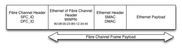
What About FCoE?

FCoE will share the fate of Fibre Channel. It has the same scaling, multi-node communication, multi-vendor interoperability, and dynamism problems as native Fibre Channel. Multi-hop FCoE never really caught on, as it didn’t end up being less expensive than Fibre Channel, and it tended to complicate operations, not simplify them. Single-hop/End-host FCoE, like the type used in Cisco’s popular UCS server system, will continue to be used in environments where blades need Fibre Channel connectivity. But again, I think that need has peaked, or will peak shortly.

Fibre Channel isn’t going anywhere anytime soon, just like Unix servers can still be found in many datacenters. But I think we’ve just about hit the peak. The workload requirements have shifted. It’s my belief that for the current/older generation of workloads (bare metal, traditional/pet virtualization), Fibre Channel is the best platform. But as we transition to the next generation of platforms and applications, the needs have changed and they don’t align very well with Fibre Channel’s strengths.

It’s an IP world now. We’re just forwarding packets in it.


Ethernet over Fibre Channel

Since the 80’s, Ethernet has dominated the networking world. The LAN, the WAN, and the MAN are all now dominated by Ethernet links. FIDDI, HIPPI, ATM, Frame Relay, they’ve all gone by the wayside. But there is one protocol that has stuck around to run alongside Ethernet, and that’s Fibre Channel. While Fibre Channel has mostly sat in the shadow of Ethernet, relegated to only storage traffic, it’s now poised to overtake Ethernet in the battle for the LAN. And the way that Fibre Channel is taking on Ethernet is with Ethernet over Fibre Channel.

Slide2

Suck it, Metcalfe

While Ethernet has enjoyed tremendous popularity, it has several (debilitating) limitations. For one, forwarding is haunted the possibility of a loop, and Spanning Tree Protocol is required to keep a watchful eye. Unfortunately, STP is almost as bad as a loop, with the ample opportunity for misconfigurations (rouge root bridges) and other shenanigans.  TRILL, a Layer 2 overlay for Ethernet that allows multi-pathing, hasn’t found its way into a commercial product yet, and its derivatives (FabricPath from Cisco and VCS from Brocade) haven’t seen much in the way of adoption.

Rathern than pile fix upon fix on Ethernet, SAN administrators (known for being the loose canons of the data center) are making a bold push to take over LAN networks as well… and they’re winning.

The T17 committe had been established by the INCITS, which is the standards body that is responsible for Fibre Channel, FCoE, and now EoFC. The T17 is responsible for all the specifications around EoFC, and in particular the interface between the two.

We really have a lot of advantages over Ethernet in terms of topology and forwarding. For one, we’re a lossless network, providing a lot more reliability than a traditional Ethernet network. We also have multi-pathing built in with FSPF routing, while still providing Layer 2 adjacencies that are still required by the old crusty crapplications that are still on people’s networks, somehow.” -John Etherman, T17 committee chair.

They’ve made a lot of progress in a relatively short time, from ironing out the specifications to getting ASICs spun, and their work is bearing fruit. Products are starting to ship, and several marquee clients have announced fabrics built entirely with EoFC.

A Day in the life of a EoFC Frame

To keep compatibility with older Ethernet/TCP/IP stacks, CNHs (Converged Network HBAs) provide Ethernet interfaces to the host operating system. The frame is formed by the host, and the CNH encapsulates the Ethernet frame into a Fibre Channel frame. Since standard Ethernet MTU is only 1500 bytes, they fit quite nicely into the maximum 2048 byte Fibre Channel frame. The T13 working group also provides specifications for Jumbo Ethernet frames up to 9216 bytes, by either fragmenting the frame into multiple 2048-byte Fibre Channel frames,

WWPNs are derived from the MAC addresses that the hosts sees. Since MAC addresses aren’t a full 64-bits, the T17 working group has allocated the 80:08 prefix to EoFC. So if your MAC address was 00:25:B6:01:23:45, the WWPN would be 80:08:00:25:B6:01:23:45. This keeps the EoFC WWPNs out of the range of the initiators (starting with 1 or 2) and targets (starting with 5).

EoFC

FC_IDs are assigned to the WWPNs on a transitory basis, and are what the Fibre Channel headers have in terms of source/destination addresses. When the Fibre Channel frame reaches its destination NX_Port (Node LAN port), the Ethernet frame is de-encapsulated from the Fibre Channel frame, and the hosts networking stack takes care of the rest. From a host’s perspective, it has no idea the transport is Fibre Channel.

Reliability

The biggest benefit to EoFC is the lossless network that Fibre Channel provides. Since the majority of traffic is East/West in modern data center workloads, busy hosts can suffer from an incast problem, where the buffers can be overloaded as a single 10 Gigabit link receives packets from multiple sources, all operating at 10 Gigabit. Fibre Channel transport provides port to port flow control, and can ensure that nothing gets dropped.

Configuration

Configuration of EoFC is fairly straightforward. I’ve got access to a new Nexus 8008, with a 32 Gbit EoFC line card that I’ve connected to a Cisco C-series server with a CNH.

nexus1# feature eofc
EoFC feature checked out
Loading Ethernet module...
Loading Spanning Tree module...
Loading LLDP...
Grace period license remaining: 110 days

nexus1# vlan 10
nexus1(vlandb)# vsan 10
nexus1(vsandb)# 10 name Storage-A
nexus1(vsandb)# vsan 1010
nexus1(vsandb)# vsan 1010 name Ethernet transport
nexus1(vsandb)# eofc vlan 10
nexus1(vsandb)# interface veth1
nexus1(vif)# switchport
nexus1(vif)# switchport mode access
nexus1(vif)# switchport access vlan 10
nexus1(vif)# bind interface fc1/1
nexus1(vif)# no shut
nexus1(vif)# int fc1/1
nexus1(if)# switchport mode F
nexus1(if)# switchport allowed vsan 10,1010
nexus1(if)# no shut 

Doing a show interface shows me that my connection is live.

 nexus1# show interface ethernet veth1 
 vEthernet1 is up
 Hardware: 1000/10000 Ethernet, address: 000d.ece7.df48 (bia 000d.ece7.df48)
 Attached to: fc1/1 (pWWN: 80:08:00:0D:EC:E7:DF:48)
 MTU 1500 bytes, BW 10000000 Kbit, DLY 10 usec,
 reliability 255/255, txload 1/255, rxload 1/255
 Encapsulation EoFC/ARPA
 Port mode is EoFC
 full-duplex, 32 Gb/s, media type is 1/2/4/8/16/32g
 Beacon is turned off
 Input flow-control is off, output flow-control is off
 Rate mode is dedicated
 Switchport monitor is off
 Last link flapped 09:03:57
 Last clearing of "show interface" counters never
 30 seconds input rate 2376 bits/sec, 0 packets/sec
 30 seconds output rate 1584 bits/sec, 0 packets/sec
 Load-Interval #2: 5 minute (300 seconds)
 input rate 1.58 Kbps, 0 pps; output rate 792 bps, 0 pps
 RX
 0 unicast packets 10440 multicast packets 0 broadcast packets
 10440 input packets 11108120 bytes
 0 jumbo packets 0 storm suppression packets
 0 runts 0 giants 0 CRC 0 no buffer
 0 input error 0 short frame 0 overrun 0 underrun 0 ignored
 0 watchdog 0 bad etype drop 0 bad proto drop 0 if down drop
 0 input with dribble 0 input discard
 0 Rx pause
 TX
 0 unicast packets 20241 multicast packets 105 broadcast packets
 20346 output packets 7633280 bytes
 0 jumbo packets
 0 output errors 0 collision 0 deferred 0 late collision
 0 lost carrier 0 no carrier 0 babble
 0 Tx pause
 1 interface resets
 switch#

Speeds and Feeds

EoFC is backwards compatible with 1/2/4/8 and 16 Gigabit Fibre Channel, but it’s really expected to take off with the newest 32/128 Gbit interfaces that are being released from vendors like Cisco, Juniper, and Brocade. Brocade, QLogix, Intel, and Emulex are all expected to provide CNHs operating at 32 Gbit speeds, with 32 and 128 Gbit interfaces on line cards and fixed switches to operate as ISLs.

Nexus 8009

Nexus 8008: 384 ports of 32 Gbit EoFC

Switches are already shipping from Cisco and Brocade, with Juniper to release their newest QFC line before the end of Q2.

Fibre Channel and FCoE: Some Basics

There’s been some misconceptions and misinformation lately about FCoE. Like any technology, there are times when it makes sense and times when it doesn’t, but much of the anti-FCoE talk lately has been primarily ignorance and/or wilful misrepresentation.

In an effort to fight that ignorance, I put together a quick introduction to how FC and FCoE works. They both operate on the basic premise that you can’t drop any frames. Fibre Channel was built as a lossless protocol, and with a bit of work, Ethernet can also be lossless.

Check it out:

Learn what Russ Fellows Doesn’t Know

So how’s this for a condescending tweet?

It’s from Russ Fellows, author of the infamous FCoE “study” (which has been widely debunked for its many hilarious errors):

Interesting article (check it out). But the sad/amusing irony is that he’s wrong. How is he wrong? Here’s what Russ Fellows doesn’t know about storage:

1, 2, 4, and 8 Gbit Fibre Channel (as he points out) uses 8/10 bit encoding. That means about a 20% of the bandwidth available was lost due to encoding overhead (as Russ pointed out). That’s why 8 Gbit Fibre Channel only provides 800 MB/s of connectivity, even though 8,000 Megabits per second equates to 1,000 Megabytes per second (8000 Megabits / (8 bits per byte) = 1,000 Megabytes).

With this overhead in mind, Fibre Channel was designed to give 100 MB/s for every Gigabit of speed. It never increased the baud rate to make up for the overhead.

Ethernet, on the other hand, did increase the baud rate to make up for the overhead. Gigabit Ethernet uses the same 8/10 bit encoding, but they kicked the baud rate up to 1.25 gigabaud to make up the differences. As such, Gigabit Ethernet provides true 1 gigabit of throughput, or 125 Megabytes per second.

10 Gigabit Ethernet moved to 64/66 encoding, and kept to the approach of not letting the overhead impact throughput. 10 Gigabit Ethernet then provides 1250 Megabytes per second of throughput. The baud rate is 10.3125, giving true 10 Gigabit per second of data.

When Fibre Channel moved to the more efficient 64/66 bit encoding, rather than change the 100 MB/s per gigabit to 125 MB/s (which you get with all Ethernet speeds), they left the ratio (1 Gigabit to 100 MB/s) the same. Thus, every Gigabit = 100 MB/s, just like in previous speeds (1/2/4/8 FC). So while 16 Gbit Fibre Channel provides 1600 MB/s of throughput, the baud rate is actually only 14 gigabaud, and not true 16 Gbit. And don’t take my word for it, check out page 7 of Scott Shimomura‘s (of Brocade) presentation at the SPDE conference.

  • 1 Gbit Fibre Channel = 100 MB/s
  • 1 Gbit Ethernet = 125 MB/s
  • 2 Gbit Fibre Channel = 200 MB/s
  • 4 Gbit Fibre Channel = 400 MB/s
  • 8 Gbit Fibre Channel = 800 MB/s
  • 10 Gbit Ethernet/FCoE = 1250 MB/s
  • 16 Gbit Fibre Channel = 1600 MB/s

10 Gigabit Ethernet provides 1250 MB/s, providing true 10 Gigabit Ethernet, and not putting the slight overhead into the equation. So while 10 Gigabit Ethernet is true 10 Gigabit, 16 Gigabit Fibre Channel is actually 14 Gigabit Fibre Channel (14.025, to be exact).

And that’s what Russ Fellows doesn’t know. His entire article is based on a false premise: Thinking that the move to 64/66 makes 16 Gbit pass more than twice as much traffic as 8 Gbit. But it’s not. He says that with 8 Gbit FC, 1+1 = 1.6 (when compared to 16 Gbit FC), which is factually incorrect for the reasons I’ve just explained. Yes, 64/66 bit encoding is more efficient. But they dropped the baud rate, negating the efficiency gains

8 Gigabit Fibre Channel provides 800 Megabytes per second of data transfer. 16 Gigabit Fibre Channel (really 14 Gigabit Fibre Channel) provides 1600 Megabytes per second of data transfer. 800 + 800 = 1600.

Sorry Russ, 1+1 really does equal 2. Even in Fibre Channel.

micdrop

Top 5 Reasons The Evaluator Group Screwed Up

It’s been a while since the trainwreck of a “study” commissioned by Brocade and performed by The Evaluator Group,  but it’s still being discussed in various storage circles (and that’s not good news for Brocade). Some pretty much parroted the results, seemingly without reading the actual test. Then got all pissy when confronted about it.  I did a piece on my interpretations of the results, as did Dave Alexander of WWT and J Metz of Cisco. Our mutual conclusion can be best summed up with a single animated GIF.


bullshit

But since a bit of time has passed, I’ve had time to absorb Dave and J’s opinions, as well as others, I’ve come up with a list of the Top 5 Reasons by The Evaluator Group Screwed Up. This isn’t the complete list, of course, but some of the more glaring problems. Let’s start with #1:

Reason #1: I Have No Idea What I’m Doing

Their hilariously bad conclusion to the higher variance in response times and higher CPU usage was that it was the cause of the software initiators. Except, they didn’t use software initiators. The had actually configured hardware initiators, and didn’t know it. Let that sink in: They’re charged with performing an evaluation, without knowing what they’re doing.

The Cisco UCS VIC 1240 hardware CNA’s were utilized.  Referring to them as software initiators caused some confusion. The Cisco VIC is a hardware initiator and we configured them with virtual HBAs. Evaluator Group has no knowledge of the internal architecture of the VIC or its driver.  Our commentary of the possible cause for higher CPU utilization is our opinion and further analysis would be required to pinpoint the specific root cause.

Of course, it wasn’t the software initiator. They didn’t use a software initiator, but they were so clueless, they didn’t know they’d actually used a hardware initiator. Without knowing how they performed their tests (since they didn’t publish their methodology) it’s purely speculation, but it looks like the problem was caused by congestion (from them architecting the UCS solution incorrectly).

Reason #2: They’re Hilariously Bad At Math.

They claimed FCoE required 50% more cables, based on the fact that there were 50% more cables in the FCoE solution than the FC solution. Which makes sense… except that the FC system had zero Ethernet.

That’s right, in the HP/Fibre Channel solution, each blade had absolutely zero Ethernet connectivity. In the Cisco UCS solution, every blade had full Ethernet and Fibre Channel connectivity.  None. Zilch. Why did they do that? Probably because had they included any network connectivity to the HP system, the cable count would have shifted to FCoE’s favor.  Let me state this again, because it’s astonishingly stupid: They claimed FCoE (which included Ethernet and FC connectivity) required more cables without including any network connectivity for the HP/FC system. 

not_even_mad

Also, they made some power/cooling claims, despite the fact that the UCS solution didn’t require a separate FC switch (it’s capable of being a full-fledged Fibre Channel switch by itself), though the HP solution would have required a separate pair of Ethernet switches (which wasn’t included). So yeah, their math is a bit off. Had they done things, you know, correctly, the power, cooling, and cable count would have flipped in favor of FCoE.

Reason #3: UCS is Hard, You Guys!

They whinged about UCS being more difficult to setup. Anytime you’re dealing with unfamiliar technology, it’s natural that it’s going to be more difficult. However, they claimed that they had zero experience with HP as well (seriously, who at Brocade hired these guys?) How easy is UCS? Here is a video done from Amsterdam where a couple of Cisco techs added a new chassis and blade and had it booted up and running ESXi in less than 30 minutes from in the box to booted. Cisco UCS is different than other blade systems, but it’s also very easy (and very quick) to stand up. And keep in mind, the video I linked was done in Amsterdam, so they were probably baked   

Reason #4: It Contradicts Everyone Else’s Results (Especially those that know what they’re doing)

For the past couple of years, VMware and NetApp have been doing performance tests on various storage protocols. Here’s one from a few years ago, which includes (native) 4 and 8 Gbit Fibre Channel, 10 Gbit FCoE, 10 Gbit iSCSI, and 10 Gbit NFS. The conclusion? The protocol doesn’t much matter. They all came out about the same when normalized for bandwidth. The big difference is in the storage backend. At least they published their methodology (I’m looking at you, Evaluator Group). Here’s one from Demartek that shows a mixture of storage protocols saturating 10 Gbit Ethernet. Again, the limitation is only the link speed itself, not the protocol. And again, again, Demartek published their methodology.

Reason #5: How Did They Set Everything Up? Magic!

Most of the time with these commissioned reports, the details of how it’s configured are given so that the results can be reproduced and audited. How did the Evaluator Group set up their environment?

GOB.MAGIC_.GIF_

As far as I can tell, magic. There’s several things they could have easily gotten wrong with the UCS setup, and given their mistake about software/hardware initiators, quite likely. They didn’t even mention which storage vendor they used.

So there you have it. A bit of a re-hash, but hey, it was a dumb report. The upside though is that it did provide me with some entertainment.

Fibre Channel: The Heart of New SDN Solutions

From Juniper to Cisco to VMware, companies are spouting up new SDN solutions. Juniper’s Contrail, Cisco’s ACI, VMware’s NSX, and more are all vying to be the next generation of data center networking. What is surprising, however, is what’s at the heart of these new technologies.

Is it VXLAN, NVGRE, Openflow? Nope. It’s Fibre Channel.

Seriously.

If you think about it, it makes sense. Fibre Channel has been doing fabrics since before we ever called Ethernet fabrics, well, fabrics. And this isn’t the first time that Fibre Channel has shown up in unusual places. There’s a version of Fibre Channel that runs inside certain airplanes, including jet fighters like the F-22.

1_FW_F-22_Raptor_participates_in_Red_Flag

Keep the skies safe from FCoE (sponsored by the Evaluator Group)

New generation of switches have been capable of Data Center Bridging (DCB), which enables Fibre Channel over Ethernet. These chips are also capable of doing native Fibre Channel So rather than build complicated VPLS fabrics or routed networks, various data center switching companies are leveraging the inherent Fibre Channel capabilities of the merchant silicon and building Fibre Channel-based underlay networks to support an IP-based overlay.

Buffer-to-buffer (B2B) credit system and losslessness of Fibre Channel, plus the new 32/128 Gigabit interfaces with the newest Fibre Channel standard are all being leveraged for these underlays. I find it surprising that so many companies are adopting this, you’d think it’d be just Brocade. But Cisco, Arista (who notoriously shunned FCoE) and Juniper are all on board with new or announced SDN offerings that are based mostly or in part on Fibre Channel.

However, most of the switches from various vendors are primarily Ethernet today, so the 10/40 Gigabit interfaces can run FCoE until more switches are available with native FC interfaces. Of course, these switches will still be required to have a number of native Ethernet ports in order to connect to border networks that aren’t part of the overlay network, so there will be still a need for Ethernet. But it seems the market has spoken, and they want Fibre Channel.


Changing Data Center Workloads

Networking-wise, I’ve spent my career in the data center. I’m pursuing the CCIE Data Center. I study virtualization, storage, and DC networking. Right now, the landscape in the network is constantly changing, as it has been for the past 15 years. However, with SDN, merchant silicon, overlay networks, and more, the rate of change in a data center network seems to be accelerating.

speed

Things are changing fast in data center networking. You get the picture

Whenever you have a high rate of change, you’ll end up with a lot of questions such as:

  • Where does this leave the current equipment I’ve got now?
  • Would SDN solve any of the issues I’m having?
  • What the hell is SDN, anyway?
  • I’m buying vendor X, should I look into vendor Y?
  • What features should I be looking for in a data center networking device?

I’m not actually going to answer any of these questions in this article. I am, however, going to profile some of the common workloads that you find in data centers currently. Your data center may have one, a few, or all of these workloads. It may not have any of them. Your data center may have one of the workloads listed, but my description and/or requirements is way off. All certainly possible. These are generalizations, and with all generalizations your mileage may vary. With that disclaimer out of the way, strap in. Let’s go for a ride.

Traditional Virtualization

It’s interesting to say that something which only exploded into the data center in a big way in about 2008 as now being “traditional”, rather than “new-fangled”. But that’s the situation we have here. Traditional virtualization workload  is centered primarily around VMware vSphere. There are other traditional virtualization products of course, such as Red Hat’s RHEV, Xen, and Microsoft Hyper-V, but VMware has the largest market share for this by far.

  • Latency is not a huge concern (30 usecs not a big deal)
  • Layer 2 adjacencies are mandatory (required for vMotion)
  • Large Layer 2 domains (thousands of hosts layer 2 adjacent)
  • Converged infrastructures (storage and data running on the same wires, FCoE, iSCSI, NFS, SMB3, etc.)
  • Buffer requirements aren’t typically super high. Bursting isn’t much of an issue for most workloads of this type.
  • Fibre Channel is often the storage protocol of choice, along with NFS and some iSCSI as well

Cisco has been especially successful in this realm with the Nexus line because of vPC, FabricPath, OTV and (to a much lesser extent) LISP, as they address some of the challenges with workload mobility (though not all of them, such as the speed of light). Arista, Juniper, and many others also compete in this particular realm, but Cisco is the market leader.

With the multi-pathing Layer 2 technologies such as SPB, TRILL, Cisco FabricPath, and Brocade VCS (the latter two are based on TRILL), you can build multi-spine leaf/spine networks/CLOS networks that you can’t with spanning-tree based networks, even with MLAG.

This type of network is what I typically see in data centers today. However, there is a shift towards Layer 3 networks and cloud workloads over traditional virtualization, so it will be interested to see how long traditional virtualization lasts.

VDI

VDI (Virtual Desktops) are a workload with the exact same requirements as traditional virtualization, with one main difference: The storage requirements are much, much higher.

  • Latency is not as important (most DC-grade switches would qualify), especially since latency is measured in milliseconds for remote desktop users
  • Layer 2 adjacencies are mandatory (required for vMotion)
  • Large Layer 2 domains
  • Converged infrastructures
  • Buffer requirements aren’t typically very high
  • High-end storage backends. All about the IOPs, y’all

For storage here, IOPs are the biggest concern. VDI eats IOPs like candy.

Legacy Workloads

This is the old, old school. And by old school, I mean late 90s, early 2000s. Before virtualization changed the landscape. There’s still quite a few crusty old servers, with uptimes measured in years, running long-abandoned applications. The problem is, these types of applications are usually running something mission critical and/or significant revenue generating. Organizations just haven’t found a way out of it yet. And hey, they’re working right now. Often running on proprietary Unix systems, they couldn’t or wouldn’t be migrated to a virtualized environment (where it would be much easier to deal with).

The hardware still works, so why change something that works? Because it would be tough to find more. It’s also probably out of vendor-supported service.

  • Latency? Who cares. Is it less than 1 second? Good enough.
  • Layer 2 adjacencies, if even required, are typically very small, typically just needed for the local clustering application (which is usually just stink-out-loud awful)
  • 100 megabit and gigabit Ethernet typically. 10 Gigabit? That’s science-fiction talk!
  • Buffers? You mean like, what shines the floor?

buffers

My own personal opinion is that this is the only place where Cisco Catalyst switches belong in a data center, and even then only because they’re already there. If you’re going with Cisco, I think everything else (and everything new) in the DC should be Nexus.

Cloud Workloads (Private Cloud)

If you look at a cloud workload, it looks very similar to the previous traditional virtualization workload. They both use VMs sitting on top of hypervisors. They both have underlying infrastructure of compute, network, and storage to support these VMs. The difference is primarily is in the operational model.

It’s often described as the difference between pets and cattle. With traditional virtualization, you have pets. You care what happens to these VMs. They have HA and DRS and other technologies to care for them. They’re given clever names, like Bart and Lisa, or Happy and Sleepy. With cloud VMs, they’re not given fun names. We don’t do vMotion/Live Migration with them. When we need them, they’re spun up. When they’re not, they’re destroyed. We don’t back them up, we don’t care if the host they reside on dies so long as there are other hosts carrying the workload. The workload is automatically sharded across the available hosts using logic in the application. Instead of backups, templates are used to create new VMs when the workload increases. And when the workload decreases, some of the VMs get destroyed. State is not kept on any single VM, instead the state of the application (and underlying database) is sharded to the available systems.

This is very different than traditional virtualization. Because the workload distribution is handled with the application, we don’t need to do vMotion and thus have Layer 2 adjacencies. This makes it much more flexible for the network architects to put together network to support this type of workload. Storage with this type of workload also tends to be IP-based (NFS, iSCSI) rather than FC-based (native Fibre Channel or FCoE).

With cloud-based workloads, there’s also a huge self-service component. VMs are spun-up and managed by developers or end-users, rather than the IT staff. There’s typically some type of portal that end-users can use to spin up/down resources. Chargebacks are also a component, so that even in a private cloud setting, there’s a resource cost associated and can be tracked.

OpenStack is a popular choice for these cloud workloads, as is Amazon and Windows Azure. The former is a private cloud, with the later two being public cloud.

  • Latency requirements are mostly the same as traditional virtualization
  • Because vMotion isn’t required, it’s all Layer 3, all the time
  • Storage is mostly IP-based, running on the same network infrastructure (not as much Fibre Channel)
  • Buffer requirements are typically the same as traditional virtualization
  • VXLAN/NVGRE burned into the chips for SDN/Overlays

You can use much cheaper switches for this type of network, since the advanced Layer 2 features (OTV, FabricPath, SPB/TRILL, VCS) aren’t needed. You can build a very simple Layer 3 mesh using inexpensive and lower power 10/40/100 Gbit ports.

However, features such as VXLAN/NVGRE encap/decap is increasingly important. The new Trident2 chips from Broadcom support this now, and several vendors, including Cisco, Juniper, and Arista all have switches based on this new SoC (switch-on-chip) from Broadcom.

High Frequency Trading

This is a very specialized market, and one that has very specialized requirements.

  • Latency is of the utmost concern. To the point of making sure ports are on the same ASIC. Latency is measured in nano-seconds, microseconds are an eternity
  • 10 Gbit at the very least
  • Money is typically not a concern
  • Over-subscription is non-existent (again, money no concern)
  • Buffers are a trade off, they can increase latency but also prevent packet loss

This is a very niche market, one that Arista dominates. Cisco and a few other vendors have small inroads here, using the same merchant silicon that Arista uses, however Arista has had huge experience in this market. Every tick of the clock can mean hundreds of thousands of dollars in a single trade, so companies have no problem throwing huge amounts of money at this issue to shave every last nanosecond off of latency.

Hadoop/Big Data

  • Latency is of high concern
  • Large buffers are critical
  • Over-subscription is low
  • Layer 2 adjacency is neither required nor desired
  • Layer 3 Leaf/spine networks
  • Storage is distributed, sharded over IP

Arista has also extremely successful in this market. They glue PC RAM onto their switch boards to provide huge buffers (around 760 MB) to each port, so it can absorb quite a bit of bursty traffic, which occurs a lot in these types of setups. That’s about .6 seconds of buffering a 10 Gbit link. Huge buffers will not prevent congestion, but they do help absorb situations where you might be overwhelmed for a short period of time.

Since nodes don’t need to be Layer 2 adjacent, simple Layer 3 ECMP networks can be created using inexpensive and basic switches. You don’t need features like FabricPath, TRILL, SPB, OTV. Just fast, inexpensive, low power ports. 10 Gigabit is the bare minimum for these networks, with 40 and 100 Gbit used for connectivity to the spines. Arista (especially with their 7500E platform) does very well in this area. Cisco is moving into this area with the Nexus 9000 line, which was announced late last year.


Conclusions

Understanding the requirements for the various workloads may help you determine the right switches for you. It’s interesting to see how quickly the market is changing. Perhaps 2 years ago, the large-Layer 2 networks seemed like the immediate future. Then all of a sudden Layer 3 mesh networks became popular again. Then you’ve got SDN like VMware’s NSX and Cisco’s ACI on top of that. Interesting times, man. Interesting times.

FCoE versus FC Farce (I’m Tellin’ All Y’All It’s Sabotage!)

Updates 2/6/2014:

  • @JohnKohler noticed that the UCS Manager screenshot used (see below) is from a UCS Emulator, not any system they used for testing.
  • Evaluator Group promises answers to questions that both I and Dave Alexander (@ucs_dave) have brought up.

On my way back from South America/Antarctica, I was pointed to a bake-off/performance test commissioned by Brocade and performed by a company called Evaluator Group. It compared the performance of edge FCoE (non-multi-hop FCoE) to native 16 Gbit FC. The FCoE test was done on a Cisco UCS blade system connecting to a Brocade switch, and the FC was done on an HP C7000 chassis system connecting to the same switch. At first glance, it would seem to show that FC is superior to FCoE for a number of reasons.

I’m not a Cisco fanboy, but I am a Cisco UCS fanboy, so I took great interest in the report. (I also work for a Cisco Learning Partner as an instructor and courseware developer.) But I also like Brocade, and have a huge amount of respect for many of Brocade employees that I have met over the years. These are great and smart people, and they serve their customers well. 

First, a little bit about these types of reports. They’re pretty standard in the industry, and they’re commissioned by one company to showcase superiority of a product or solution against one or more of their competitors. They can produce some interesting information, but most of the time it’s a case of: “Here’s our product in a best-case scenario versus other products in a mediocre-to-worst case scenario.” No company would release a test showing other products superior to theirs of course, so they’re only released when a particular company comes out on top, or (most likely) the parameters are changed until they do. As such, they’re typically taken with a grain of salt. In certain markets, such as the load balancer market, vendors will make it rain with these reports on a regular basis. 

But for this particular report, I found several substantial issues with it which I’d like to share. It’s kind of a trainwreck. Let’s start with the biggest issue, one that is rather embarrassing.

What The Frak?

On page 17 check out the Evaluator Group comments:

“…This indicates the primary factor for higher CPU utilization within the FCoE test was due to using a software initiator, rather than a dedicated HBA. In general, software initiators require more server CPU cycles than do hardware initiators, often negating any cost advantages.”

For one, no shit. Hardware initiators will perform better than software initiators. However, the Cisco VIC 1240 card (which according to page 21 was included in the UCS blades) is a hardware initiator card. Being a CNA (converged network adaptor) the OS would see a native FC interface. With ESXi you don’t even need to install extra drivers, the FC interfaces just show up. Setting up a software FCoE initiator would actually be quite a bit more difficult to get going, which might account for why it took so long to configure UCS. Configuring a hardware vHBA in UCS is quite easy (it can be done in literally less than a minute).

Using software initiators against hardware FC interfaces is beyond a nit-pick in a performance test. It would be downright sabotage.

sabotage

I asked the @Evalutor_Group account if they really did software initiators:

And they responded in the affirmative.

Wow. First of all, software FCoE initiators is absolutely not standard configuration for UCS. In the three years I’ve been configuring and teaching UCS, I’ve never seen or even heard of FCoE software initiators being used, either in production or in a testing environment. The only reason you *might* want to do FCoE software initiators is when you’ve got the Intel mezzanine card (which is not a CNA, just an Ethernet card), and want to test FCoE. However, on page 21 it shows the UCS blades has having the VIC 1240 cards, not the Intel card.

So where were they getting that it was standard configuration?

They countered with a reference to a UCS document regarding the VIC:

and then here:

Which is this document here.

The part they referenced is as follows:

The adapter offerings are:

■ Cisco Virtual Interface Cards (VICs)

Cisco developed Virtual Interface Cards (VICs) to provide flexibility to create multiple NIC and HBA devices. The VICs also support adapter Fabric Extender and Virtual Machine Fabric Extender technologies.

■ Converged Network Adapters (CNAs)

Emulex and QLogic Converged Network Adapters (CNAs) consolidate Ethernet and Storage (FC) traffic on the Unified Fabric by supporting FCoE.

■ Cisco UCS Storage Accelerator Adapters

Cisco UCS Storage Accelerator adapters are designed specifically for the Cisco UCS B-series M3 blade servers and integrate seamlessly to allow improvement in performance and relief of I/O bottlenecks.

Wait… I think they think that the VIC card is a software-only FCoE card. It appears they came to that conclusion because the VIC doesn’t specifically mention it’s a CNA in this particular document (other UCS documents clearly and correctly indicate that the VIC card is a CNA). Because it mentions the VICs separately from the traditional CNAs from Emulex and Qlogic, it seems they believe it not to be a CNA, and thus a software card.

So it may be they did use hardware initiators, and mistakenly called them software initiators. Or they actually did configure software initiators, and did a very unfair test.

No matter how you slice it, it’s troubling. On one hand, if they did configure software initiators, they either ignorantly or willfully sabotaged the FCoE results. If they just didn’t understand the basic VIC concept, it means they setup a test without understand the most basic aspects of the Cisco UCS system. We’re talking 101 level stuff, too.  I suspect it’s the later, but since the only configuration of any of the devices they shared was a worthless screenshot of UCS manager, I can’t be sure.

This lack of understanding could have a significant impact on the results. For instance, on page 14 the response time starts to get worse for FCoE at about the 1200 MB/s mark. That’s roughly the max for a single 10 Gbit Ethernet FCoE link (1250 MB/s). While not definitive, it could mean that the traffic was going over only one of the links from the chassis to the Fabric Interconnect, or the traffic distribution was way off. My guess is they didn’t check the link utilization, or even know how, or how to fix it if it were off.

Conclusions First?

One of the more odd aspects of this report are where you found some of the conclusions, such as this one:

“Evaluator Group believes that Fibre Channel connectivity is required in order to achieve the full benefits that solid-state storage is able to provide.”

That was page 1. The first page of the report is a little weird to make a conclusion like that. Makes you sound a little… biased. These reports usually try to be impartial (despite being commissioned by a particular vendor). This one starts right out with an opinion.

Lack of Configuration

The amount of configuration they provide for the setup very sparse. For the UCS side, all they provide is one pretty worthless screenshot. Same for the HP system. For the UCS part, it would be important to know how they configured the vHBAs, and how they configured the two 10 Gbit links from the IOM to the chassis. Where they configured for the preferred Fabric Port Channel, or static pinning? So there’s no way to duplicate this test. That’s not very transparent.

Speaking of configuration, one of the issues they had with the FCoE side was how long it took them to stand up a UCS system. On page 11, second paragraph, they mention they need the help of a VAR to get everything configured. They even made a comment on page 10:

“…this approach was less intuitive during installation than other enterprise systems Evalutor Group has tested.”

youdontsay

So wow, you’ve got an environment that you’re unfamiliar with (we’ll see just how unfamiliar in a minute), and it took you *gasp* longer to configure? I’m a bit of an expert on Cisco UCS. I’m kind of a big deal. I have many paper-bound UCS books and my apartment smells of rich mahogany. I teach it regularly. And I’m not nearly as familiar with the C7000 system from HP, so I’d be willing to bet that it would take me longer to stand up an HP system than it would a Cisco UCS system. Anyone want in on that action?

Older Version? Update 2-6-2014: Screenshot Is A Fake

itsafake

@JohnKohler noticed that on the screenshot on page 23 that the serial number in the screenshot is “1”, which means the screenshot is not from any physical instance of a UCS Manager, but the UCS Emulator. The date (if accurate on the host machine) shows June of 2010, so it’s a very, very old screenshot (probably of 1.3 or 1.4). So we have no idea what version of UCS they used for these tests (and more importantly, how they were configured). 

Based on the screenshot on page 23, the UCS version is 2.0. How can you tell? Take a look where it says “Unconfigured Ports”. As of 2.1, Cisco changed the way ports are shown in the GUI. 2.1 and later do not have a sub-menu for unconfigured ports. Only 2.0 and prior.

nounconfiguredports

In version 2.1, there’s no “Unconfigured Ports” sub-menu. 

evalgroupucs

From Page 21, you can see “Unconfigured Ports”, indicating it’s UCS 2.0 or earlier.

If the test was done in November 2013, that would put it one major revision behind, as 2.1 was released in November of 2012 (2.2 was released in Dec 2013). We don’t know where they got the equipment, but if it acquired anytime in the past year, it likely came with 2.1 already installed (but not definite). To get to 2.0, they’d have to downgrade. I’m not sure why they would have done that, and if they brought in a VAR with certified UCS people they would have likely recommended 2.1. With 2.1, they could have directly connected the storage array to the UCS fabric interconnects. UCS 2.1 can do Fibre Channel zoning, and can function as a standard Fibre Channel switch. The Brocade switch wouldn’t have been needed, and the links to the storage array would be 8 Gbit instead of 16 Gbit. 

They also don’t mention the solid state array vendor, so we don’t know if there was capability to do FCoE directly to the storage array. Though not terribly common yet, FCoE connection to a storage array is done in production environments and would have benefited the UCS configuration if it were possible (and would be the preferred way if competing with 16 Gbit FC). There would have been the ability to do an LACP port channel between the Fabric Interconnects, providing better load distribution and redundancy.

Power Mad

The claim that the UCS system uses more power is laughable, especially since they specifically mentioned this setup is not how it would be deployed in production. Nothing about this setup was production worthy, and it wasn’t supposed to be. It’s fine for this type of test, but not for production. It’s non-HA, and using only 2 blades would be a waste of a blade system (and power, for either HP or Cisco). If you were only using a handful of servers, buying pizza boxes would be far more economical. Blades from either HP or Cisco only make sense past a certain number to justify the enclosures, networking, etc. If you want a good comparison, do 16 blades, or 40 blades, or 80 blades. Also include the Ethernet network connectivity. The UCS configuration has full Ethernet connectivity, the HP configuration as shown has squat.

Even by competitive report standards, this one is utter bunk. If I was Brocade, I would pull the report. With all the technology mistakes and ill-found conclusions, it’s embarrassing for them. It’s quite easy for Cisco to rip it to shreds.

(Just so there’s no confusion, no one paid me or asked me to write this. In fact, I’m still on PTO. I wrote this because someone is wrong on the Internet…)

Software Defined Fowarding: What’s In A Name?

I’ve got about four or five articles on SDN/ACI and networking in my drafts folder, and there’s something that’s been bothering me. There’s a concept, and it doesn’t have a name (at least one that I’m aware of, though it’s possible there is). In networking, we’re constantly flooded with a barrage of new names. Sometimes we even give things a name that already have a name. But naming things is important. It’s like a programming pointer, a name of something will be a pointer to a specific part of our brain that contains the understanding a of a given concept.

Software Defined Forwarding

I decided SDF needed a name because I was having trouble describing a concept, a very important one, in reference to SDN. And here’s the concept, with three key aspects:

  1. Forwarding traffic in a way that is different than traditional MAC learning/IP forwarding.
  2. Forwarding traffic based on more than the usual Layer 2 and Layer 3 headers (such as VXLAN headers, TCP and/or UDP headers).
  3. Programming these forwarding rules via a centralized controller (which would be necessary if you’re going to throw out all the traditional forwarding rules and configure this in any reasonable amount of time).
  4. In the cases of Layer 2 adjancencies, multipathing is inherent (either through overlays or something like TRILL).

Throwing out traditional rules of forwarding is what OpenFlow does, and OpenFlow got a lot of the SDN ball rolling. However, SDN has gone far beyond just OpenFlow, so it’s not fair to call it just OpenFlow anymore. And SDN is now far too broad of a term to be specific to fowarding rules, as SDN encompasses a wide range of topics, from forwarding to automation/orchestration, APIs, network function virtualization (NFV), stack integration (compute, storage), etc. If you take a look at the shipping SDN product listing, many of the products don’t have anything to do with actually forwarding traffic. Also something like FabricPath, TRILL, VCS, and SPB all do Ethernet forwarding in a non-standard way, but this is different. So herein lies the need I think to define a new term.

And make no mistake, SDF (or whatever we end up calling it) is going to be an important factor in what pushes SDN from hype to implementation.

Forwarding is simply how we get a packet from here to there. In traditional networking, forwarding rules are separate by layer. Layer 2 Ethernet forwarding works in one particular way (and not a particularly intelligent way), IP routing works in another way.  Layer 4 (TCP/UDP) gets a little tricky, as switches and routers typically don’t forward traffic based on Layer 4 headers. You can do something like policy based routing, but it’s a bit combersome to setup. You also have load balancers handling some Layer 4-7 features, but that’s handled in a separate manner.

So traditional forwarding for Layer 2 and Layer 3 hasn’t changed much. For instance, take the example of a server plugging into a switch and powering up. Its IP address and MAC address haven’t been seen on the network, so the network is unaware of both the Layer 2 and Layer 3 addresses. The server is plugged it into a switch with a port set for the right VLAN. The server wants to send a packet out to the internet, so it ARPs (WHO HAS 1.1.1.1, for example). The router (or more likely, SVI) responds with its MAC address, or the floating MAC (VMAC) of the first-hop redundancy protocol, such as VRRP or HSRP. Every switch attached to that VLAN sees this ARP and ARP response, and every switches Layer 2 forwarding table learned which port to find that particular MAC address on.

tradcoreaccess

In several of the SDF implementations that I’m familiar with, such as Cisco’s ACI, NEC’s OpenFlow controller, and to a certain degree Juniper’s QFabric, things get a little weird.

dogsandcats

Forwarding in SDF/SDN, Gets A Little Weird

In the SDF (or many implementations of SDF, they differ in how they accomplish this) the local TOR/leaf switch is what answers the server’s ARP. Another server, on the same subnet and L2 segment (or increasingly a tenant), ARPs on a different leaf switch.

leafspinecray

In the diagram above, note both servers have a default gateway of 1.1.1.1. The two servers are Layer 2 adjacent, existing on the same network segment (same VLAN or VXLAN). Both ARP for their default gateways, and both receive a response from their local leaf switch with an identical MAC address. Neither server would actually see the other’s ARP, because there’s no need to flood that ARP traffic (or most other BUM traffic) beyond the port that the server is connected to. BUM traffic goes to the local leaf, and the leaf can learn and forward in a more intelligent manner. The other leaf nodes don’t need to see the flooded traffic, and a centralized controller can program the forwarding tables of the leafs and spines accordingly.

In most cases, the packet’s forwarding decision, based on a combination of Layer 2, 3, 4 and possibly more (such as VXLAN) is made at the leaf. If it’s moving past a Layer 3 segment, the TTL gets decremented. The forwarding is typically determined at the leaf, and some sort of label or header applies that contains its destination port.

You have this somewhat with a full Layer 3 leaf/spine mesh, in that the local leaf is who answers the ARP. However, in a Layer 3 mesh hosts connected to different leaf switches are on different network segments, and the leaf is the default gateway (without getting werid).  In some applications, such as Hadoop, that’s fine. But for virtualization (unfortunately) there’s a huge need for Layer 2 adjacencies. For now, at least

Another benefit of SDF is the ability to intelligently steer traffic through various network devices, known as service chaining. This is done without changing default gateways of the servers, bridging VLANs and proxy arp, or other current methodologies. Since SDF throws out the rulebook in terms of forwarding, it becomes a much simpler matter to perform traffic steering. Cisco’s ACI does this, as does Cisco vPath and VMware’s NSX.

servicechaining

A policy, programmed on a central controller, can be put in place to ensure that traffic forwards through a load balancer and firewall. This also has a lot of potential in the realm of multi-tenancy and network function virtualization. In short, combined with other aspects of SDN, it can change the game in terms of how network are architected in the near future.

SDF is only a part of SDN. By itself, it’s compelling, but as there have been some solutions on the market for a little while, it doesn’t seem to be “must have” to the point where customers are upending their data center infrastructures to replace everything. I think for it to be a must have, it needs to be a part